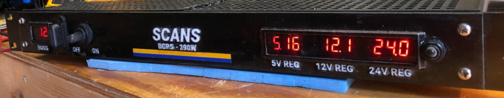
A multi-voltage DC power supply, built from commodity components, that accepts 10 to 24 volts in and will supply 5V 10A, 12V 5A, and 24V 3A for powering Raspberry Pi’s, routers, POE equipment, etc.
Disclaimer
This blog post is shared with the intent of providing insights into the design and considerations involved in building the project discussed herein. It is not a comprehensive How-To guide and does not offer step-by-step instructions for constructing or implementing the project discussed. The information is distributed in the hope that it may be useful or inspiring, but WITHOUT ANY WARRANTY; without even the implied warranty of MERCHANTABILITY or FITNESS FOR A PARTICULAR PURPOSE. Proceed at your own risk, and always take appropriate safety precautions when working on similar projects.
Introduction
The systems that I’m building for the boat: data infrastructure, sensors, navigation, etc. need a variety of different, but well regulated supply voltages. For example, the network routers need 24 volts DC, Raspberry PI’s (used in the embedded systems) need 5 VDC, LCD computer monitors need 19 VDC, the various radios need 12, etc. But the present power generation systems onboard deliver anywhere from a little under 12 to a little over 14 volts DC depending on circumstances. That voltage must be transformed into the stable DC voltages the given devices need, just as if they were plugged into the AC power grid on land using the adaptor that came with them. Note that plugging a device into a DIY power supply possibly voids the device warranty. Soooo – if you decide to make your own power supplies, you might want to make sure that new computer monitor is working and doesn’t need a warranty replacement before experimenting on it.
Before I dive into the details of the project a little background is needed regarding DC-to-DC converters and DC voltage regulators.
DC-to-DC converters are electronic circuits that convert a DC input voltage to a DC output voltage of a different level. The three common types of DC-to-DC converters are Buck, boost, and buck-boost. Each of these has a different function and are used in a variety of applications.
Buck Converter: A buck converter, also known as a step-down converter, is a DC-to-DC converter that produces an output voltage that is lower than the input voltage. So, a buck reduces the voltage, but will increase the amperage that can be supplied at the output. The buck converter is used in applications where the input voltage is higher than the required output voltage. For example: battery-powered devices, such as mobile phones, to convert the battery voltage to the voltage required by the device.
Boost Converter: A boost converter, also known as a step-up converter, is a DC-to-DC converter that produces an output voltage that is higher than the input voltage. Thus, a boost converter increases the voltage while decreasing the amperage supplied at the output. The boost converter is used in applications where the input voltage is lower than the required output voltage. Applications for boost converters include automotive and industrial applications to convert a low battery voltage to a higher voltage required by the system.
Buck-Boost Converter: A buck-boost converter is a DC-to-DC converter that can produce an output voltage that is either higher or lower than the input voltage and it will either deliver less or more current (respectively) at the output. The buck-boost converter is commonly used in applications where the input voltage may vary widely, and a stable output voltage is required. For example, it is often used in battery chargers, solar power systems, and portable electronic devices.
So what’s the difference between the DC buck-boost converter and a DC voltage regulator?
A DC voltage regulator is a circuit that maintains a constant output voltage despite changes in the input voltage or load current. The voltage regulator typically operates by varying the resistance in the circuit to adjust the voltage. Voltage regulators can be either linear or switching, and they are used in a wide range of applications, such as power supplies, audio amplifiers, and motor control circuits. However, unlike the DC-to-DC buck/boost the excess voltage is dissipated as heat, rather than being converted to current as in the buck/boost/buck-boost converter. So, using a linear regulator to a produce a stable 12 volt output when the input is 15 volts, would result in no increase in available current at the output, but would produce heat resulting from the 3VDC that would need to be dissipated through circuit’s resistance into the heat sink. Therefore, DC-to-DC converters are more efficient than regulators in many situations, including the power supply discussed in this article that converts the 11 to 15 volt mains voltage to 5VDC (buck), 12 VDC (buck-boost) and 24 VDC (boost).
The list of materials used are given in table 1, and as promised in the byline of this post, all of the critical components are off-the-shelf (commodity) parts. While I did create a few bespoke, 3D-printed parts for the build, they are cosmetic. The heart of the unit are the DC-to-DC converters which are relatively inexpensive and readily available from Amazon.Com, AliExpress, or other online retailers.
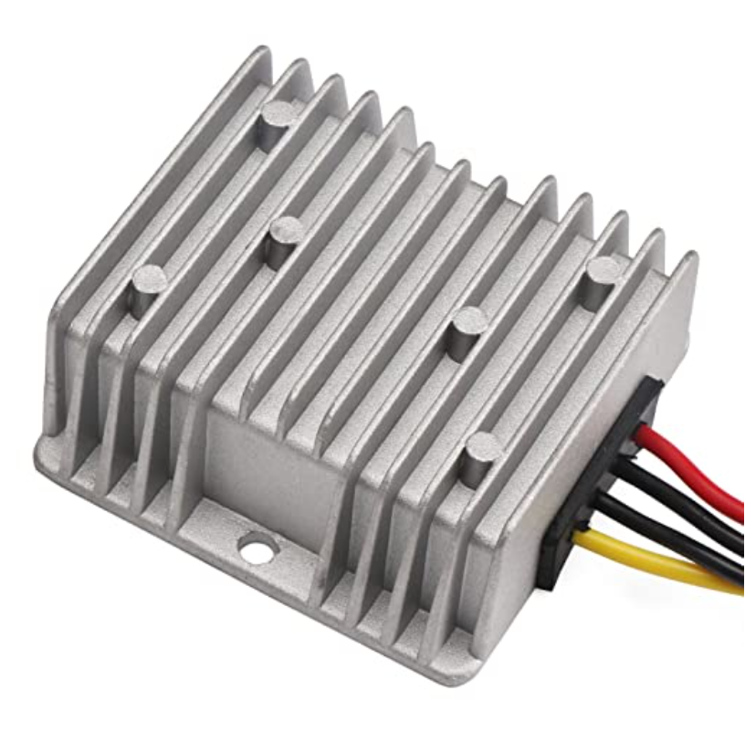
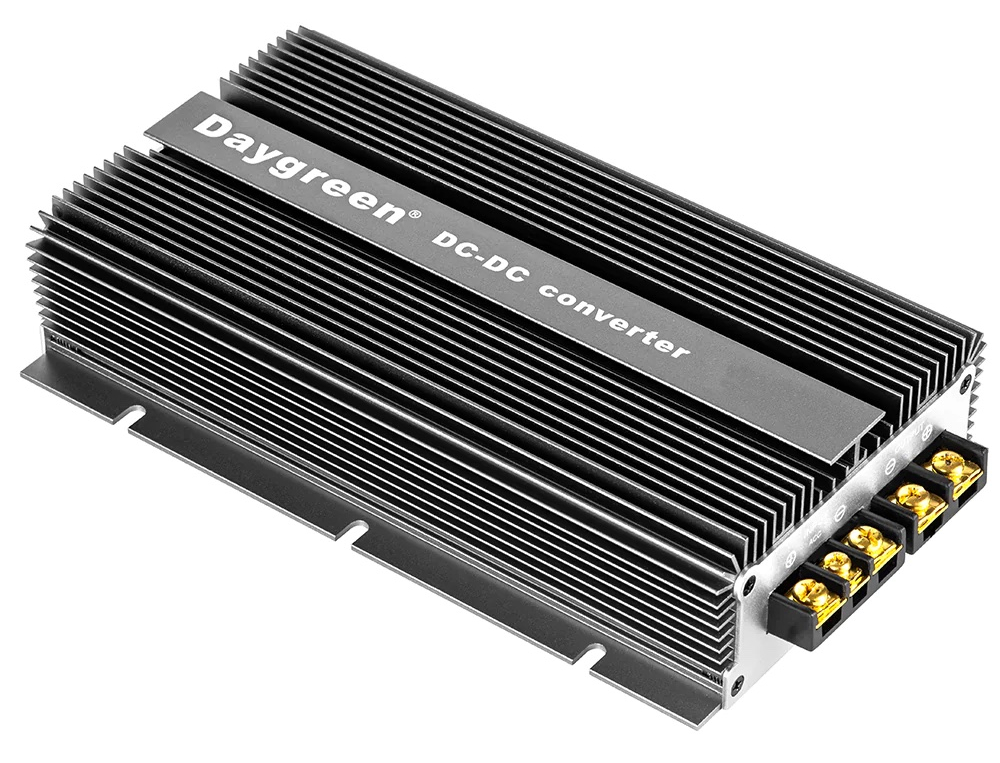
There are a wide variety of DC-to-DC converters available. The 48V power generation system I’ve begun working on for Sérénité (future post), of which the arch is the first piece (see: The Great Arch Project), will combine wind and solar to deliver upwards of 1 kWh to charge a large battery bank, and power all of the onboard DC and AC systems while away from the dock. To connect the new 48 volt system to the legacy 12 volt systems a high power 48V to 12V DC 100A buck converter such as the one shown below will be used.
DC-to-DC converters are used in a wide variety of applications including industrial, telecommunication, consumer goods, and marine electronics, They play a crucial role in adapting DC voltages to meet the requirements of different electronic systems and, when applicable, are more efficient than DC voltage regulators.
Safety Precautions
Before diving into electrical/electronics project I always take a moment to consider safety precautions. Electrical projects come with their own set of risks that should not be overlooked, not to mention I really, really don’t want to set my workshop on fire.
- Personal Protective Equipment (PPE): I always wear appropriate PPE, including safety goggles and insulated gloves, to protect against accidental shocks and flying debris.
- Work Environment: I ensure my workspace is clean, dry, and well-lit. It should be free of conductive debris like metal turnings, bits of stray wire, etc. that cousl cause an accidental short.
- Tool Safety: I use insulated tools designed for electrical work and check that they are in good condition before starting work.
- Power Off: Always disconnect the power supply before making or modifying any connections.
- Check and Double-Check: Before powering up a project, I double-check all connections to ensure they are secure and in their correct places.
- Test Runs: If possible I perform initial tests using a lower power supply. This can help identify any issues without causing damage to the components.
- Emergency Measures: I keep a fire extinguisher rated for electrical fires close at hand.
- Consult Manuals: I always read the manufacturer’s guidelines and safety instructions for each component I’m using.
By taking these precautions, you can significantly reduce the risks associated with electrical DIY projects and ensure a safer, more productive work environment.
Ok, enough said – now on to the materials and assembly
Materials
| 1 | DROK® 10361205L 12V 5A buck-boost converter |
| 1 | DROK® 5V 10A DC Voltage Buck |
| 1 | Elkin® 24V 3A DC Voltage Boost converter |
| 4 | Bayite Three-Wire DC 0~30V Red Digital Mini Voltmeter |
| 1 | BUD Industries 19″ x 4″ 1U rack mount project case |
| 1 | Fuse holder |
| 5 | Terminal blocks |
| Ancor Ring connectors | |
| Brass standoffs | |
| Marine dual wall heat shrink | |
| Ancor tinned marine wire | |
| 1 | Small switch (for displays) |
| 1 | Rubber boot for small switch |
| 1 | Tinted polycarbonate sheet (McMaster Carr) for bezel |
| 1 | Main switch |
| 1 | Rubber boot for main switch |
Assembly
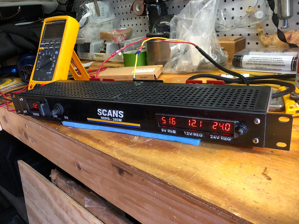
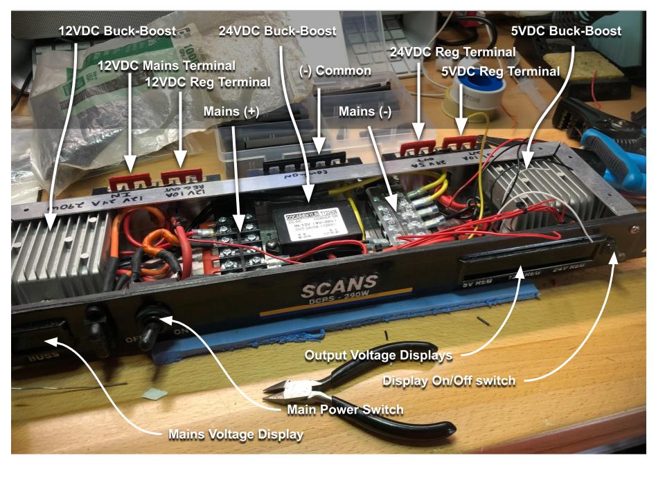
The components were mounted inside the rackmount case along with terminal blocks onto which the connections were made. The two large boost-buck converters were mounted using heatsink grease to ensure good heat transfer to the case. During testing with the unit running at rated output, no significant heating was observed – infrared thermometer 3 cm from heatsink. Terminal blocks were also mounted to the rear of the unit to provide connection points for common, unregulated 12v (mains), and regulated 5, 12, and 24 volts.
One note about the buck/boost converters used in this project: they use an odd color scheme for the DC wiring where yellow is positive and black is negative. To prevent confusion and comply with the ABYC wiring standard which specifies that DC power mains (+) should be RED and DC power mains (-) should be YELLOW, I used heat shrink tubing to cover the wiring with the appropriate color.
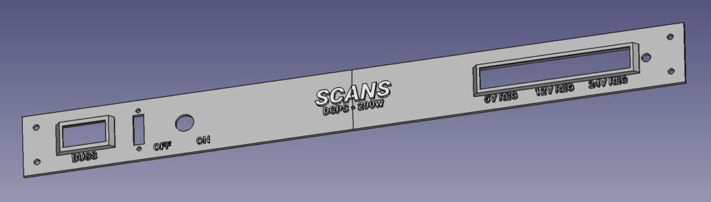
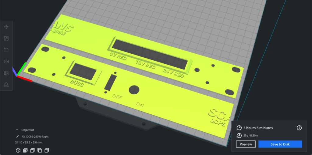
The faceplate for the unit was a bit of an experiment since I intended to use the 3D printer to create the lettering and bezel holders. After several false starts I decided to make it a two piece veneer (so it would fit on the printer) to be glued to the aluminium faceplate that is part of the project enclosure. I designed it using FreeCAD and sliced the model using Ultimaker Cura.
| “Slicing” refers to the process of subdividing a 3D model into into thin layers that are to be printed, one atop the other, on a 3D printer. It is through the process of building up layer after thin layer of fused plastic that a 3D print is formed. This additive process is called Fused Deposition Modeling or FDM. |
The faceplate veneer included the raised lettering and holders for the tinted polycarbonate bezels. I also created a flat version of the faceplate that served as the drilling guide to the aluminium faceplate.
The individual square holes were cut in the aluminium using a drill bit to rough out the hole, then a combination of rotary tool and manual file were used to bring the hole to its finished dimensions.
The faceplate was printed as two pieces in white PLA and the halves glued together using black epoxy. The epoxy also coated the entire front of the faceplate and was allowed to fully harden. The following day the front of the faceplate was wiped with acetone to remove the amine blush. Then a detail sander was used to remove the black epoxy from the top of the raised letters, exposing the white PLA beneath, thus creating the white lettering. A finishing coat of clear epoxy was applied to the letters to protect the PLA beneath. Then,
the bezels were cut from 2mm tinted polycarbonate sheet and snapped into the frame from the backside of the faceplate. The faceplate was then epoxied to the aluminium faceplate. The assembly was clamped and allowed to harden.